After doing some of the online robotics software course here I really enjoyed watching my simulated quad-copter following my instructions and moving around in MATLAB. I thought I’d like to see it in real life.
This is a log of my side-project to learn about and build aerial robots. I’ll be sharing what I learn, code and build. I’ll try my best to explain the different steps so that you can follow them to make your own. I hope you enjoy this and find it useful!
Check out this MOOC to learn how to simulate quadcopters like I did above!
Background
Elsewhere on this website I talk about (physical) urban mobility and how flying cars could be a good solution for certain segments of the grand challenge. I also review and comment on the feasibility study done by Uber Elevate.
So why don’t we just use helicopters or make them cheaper? If you’ve done any engineering, you’ll know that helicopters are difficult to design and manufacture, not very intuitive to control and quite noisy. Helicopters and large drone-like cars are also some of the most inefficient ways of transporting people, as I quantified earlier this year.
For larger VTOL aircraft, tilt-rotors seem to be the best compromise for speed and efficiency. They rotate their motors between a helicopter and a fixed-wing aircraft configuration, which adds complexity, but significantly boosts range and cruise efficiency. An example is the gorgeous (and over budget) V-22 Osprey.

For much smaller vehicles like parcel delivery drones, rescue vehicles or hobby craft, quad-copters (like retail drones) can still have a role to play. They are simple, cheap to build, and today most hobbyists can afford to buy them or build their own for prototyping and education.
Quadcopters are also fairly easy to control because they often contain many planes of symmetry, and their safety can be amplified by adding more motors (Volocopter has 18!).
So for now, I’ll be building a quadcopter drone!
*** WARNING: this blog describes a project that results in a powerful and dangerous flying robot of ~2kg and ~50,000RPM motors. Do not asseble propellers until you have read the entire Joop Brokking project. Do not fly this indoors or close to house plants, people or pets. It’s illegal to fly such a drone outdoors unless you pass the CAA Test and follow their guidance. ***
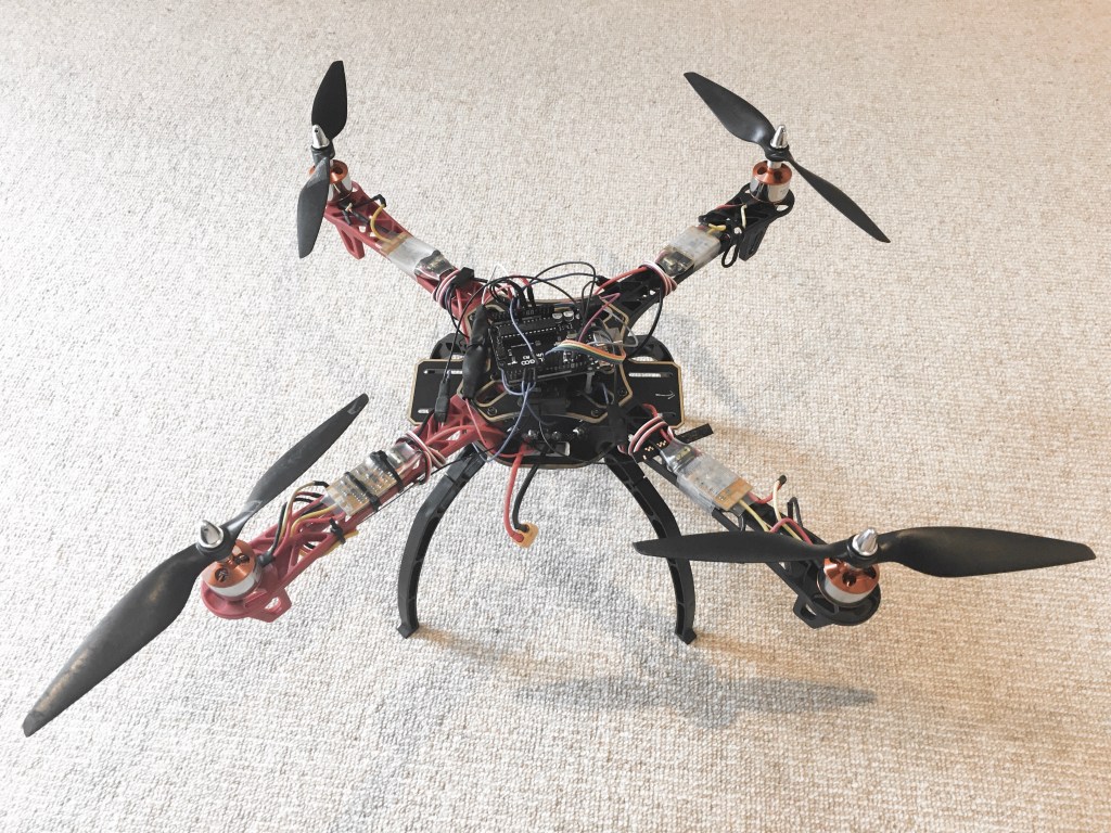
DIY Drone Project – DroneyA
To build a drone you generally need:
- Bones: Frame (or body) to hold this all together
- Heart and Lungs: Power supply, distribution and control
- A Purpose: A radio transmitter and receiver
- Eyes and Ears: Sensors
- Muscles: Motors and propellers
- Nerves: Input / Output signal connections to your Controller
- A Brain: Controller Programme (on a Flight Computer)
Now, unless you have designed your own vehicle and calculated mass, power, prop and dimensions… follow somebody else’s tutorial exactly, then make small iterations. To build a configurable one like in this blog I also strongly recommend you have:
- A fairly good understanding of C++ or Python
- Decent soldering skills (YouTube it)
- Some experience with hobby electronics
- An understanding of Drone Control Theory
- (£300 to part with for learning… the drone could crash)
Realistically, this is years of work if you’re doing it on weekends like me, but each step is a mini life skill, fun and fulfilling!
I have managed to build a programmable, hack-able, open source one (DroneyA) for around £250, excluding setup costs. It’s 95% based on this incredible tutorial by Joop Brokking for an auto-levelling quadcopter. If you’re impatient or see this as a one-off project, go ahead and follow it by all means.
There are claims you can do this for $150 but that makes some unfair assumptions (in my opinion). Before starting you’d need a basic setup (solder iron, multi meter, shrink tubing, wires, helping hands, mounting tape, spacers and bolts). To get anything decent I found this to be £80. TIP 1: Don’t buy the cheapest thing you find on Amazon, it’s littered with dangerous / fake Chinese brand solder irons.
For the actual robot hardware, nearly everything is manufactured and stocked in China. There aren’t many re-sellers in the U.K., so you’ll suffer from import/exchange rate/shipping costs for most things here (compared to the USA where there’s more variety and competition). TIP 2: Don’t buy the cheapest drone hardware you find on Amazon, lots of fake reviews especially on Chinese motors and ESCs, below I share better sources.
If you want to build something upgradable in the future, and view Joop’s drone as a first step, this blog is for you. I’ll explain what I did differently to his tutorial and why. I’ll also stop often to describe basic theory with helpful links to my site and others.
Also: I wrote my own python controllers and did a few online courses before starting Joop’s tutorial, and found that really enriched the process of following his tutorial to build my first drone. You can of course dive right in, but I really recommend you try some software and simulation first.
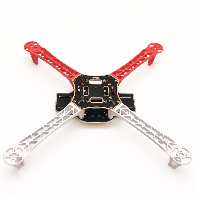
Step 1: Get a Drone Frame
In Joop’s tutorial and most other DIY drone instructables, the DJI 450 Flame quad-copter frame seems to be a popular choice. There are many clones out there for physically identical frames, and I found one for £20 off ebay. Bolt holes for motors (M3 x 6mm) and mounts (M2.5x6mm) are standard and fit all the usual hobby accessories we’ll add later.
Arms of a different colour should be on the same side — this helps you determine which way is the front.
Step 2: Wire Power Supply and Distribution
The lower frame comes with gold-plated tabs to solder on leads for a lithium ion battery, and four others (connected) running out to the arms and electronic speed controllers (ESCs). These tabs are connected in parallel through the structure of the frame, making it an inbuilt power distribution board (PDB).
The frame contains enough room between the layers to slot in a 2200mAh / 11.1V 3 cell Lithium-Ion-Phosphate battery (A LIPO) which you can secure with velcro later. The ESCs are normally mounted on the arms, but each have a live and ground power cable that need routing.
You can either solder your batteries and ESCs to the frame (example here) in which case you rely on the inbuild power distribution board (PDB) of the frame. Or, you can buy a separate PDB with bananna connectors to just plug them in.
Decide which PDB method you’ll use before buying your ESCs, as this will save you time and money later. In both cases, it’s good to buy an XT60 junction connector for the battery.
Step 3: Choose your RC Controller & Receiver
Before you start wiring the rest of the drone, you need to decide on the radio receiver we’ll use, which also means you’ll need to decide on a transmitter (remote control).
For his entry-level drone, Joop Brokking recommends you get the FlySky FS-T6 along with (I think) a Futuba R617FS receiver. He says that any 4 channel system would work (For a quadcopter this is throttle, yaw, pitch and roll).
I looked at some of Joop’s more advanced drone projects, and some advice from Adrupilot, and decided to buy the more advanced Frsky Taranis QX7 with an X8R receiver module. I got both for £130 which is a little more expensive than the recommended option.
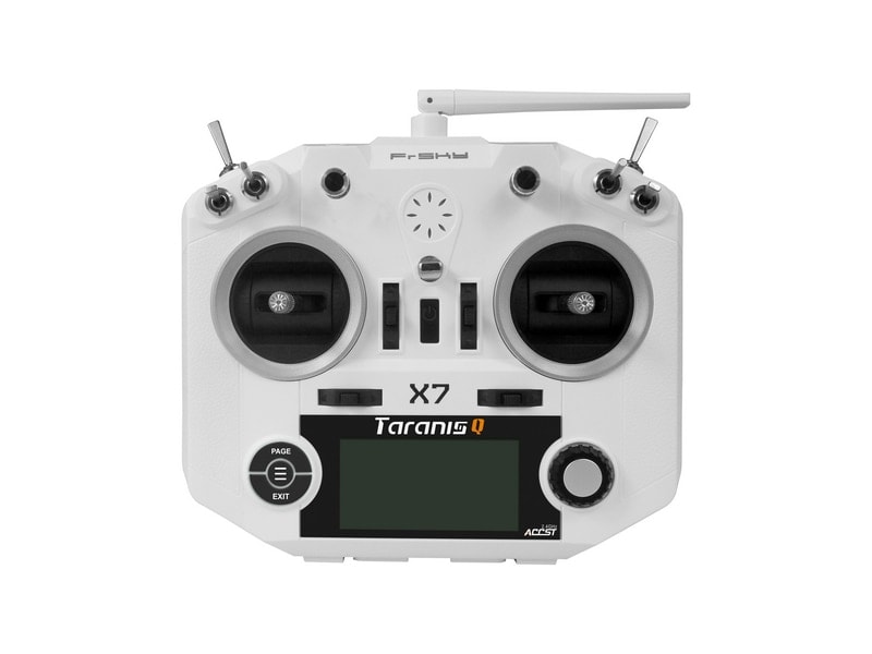
The reasons I went with the Taranis controllers is:
- It runs an open source code (OpenTx) if you want to reprogramme it
- It supports automatic telemetry through ArduPilot — this means it can read and display information from an ArduPilot Drone, not just control it
- Apparently the FS-T6 doesn’t produce PPM signals which means you need a converter or new receiver for Joop’s more advanced projects — I’ll explain a little more about PPM and PWM in the next section
So overall, if you want to build more, advanced drones in the future, the Taranis will work for all of them as it’s more modular and configurable. Telemetry is also useful for seeing things like battery level on your transmitter. The Frsky T6 maybe cheaper upfront, but you’ll spend more in total in the future if you want to continue this hobby.
Receivers can either output 4-8 single channels using 3-wire servo (PWM) connections for each, or up to 16 channels in a single signal wire (SBUS/PPM). For this project we use 4 of the the normal PWM channels, so we need a 5V power connection and 4 female-male wires to carry the signal to the arduino (next step).
I found Joop’s tutorial a little light on the detail here, so to illustrate:

You’ll need to pair your transmitter and receiver according the manual that comes with your receiver. If you use my hardware, set the transmitter to D16 mode, short the 2nd and 3rd pins (using the supplied jumper plug that comes with the receiver) and follow a tutorial like this one.
Step 4: Sensors
The most basic sensor a vehicle needs to to measure its attitude is a gyroscope. Gyrosopes measure angular acceleration. Industrial gyroscopes are hyper-accurate to control aircraft and rockets, but they are also very expensive and heavy.
For this drone we use a Micro-Electromechanical (MEMS) gyroscope called the MPU6050 which is the size of your fingertip and come with standard hobby grade connectors. They should come at around £3 a piece.
MEMS gyros are cheap and cheerful, but not really accurate enough for industrial precision. Still, for hobby drones, they do a great job. They appear solid, but they actually have micro-scale internal components that vibrate in a calibrated way to detect acceleration and rotation:
Step 5: Motors (+ Controllers and Props)
The brushless DC motors used for drones are incredibly powerful — a 30g motor can generate up to 1.2kg of thrust. They are an extension of stepper motors optimised for high speed. They have a stationary (stator) part which gets magnitised in a rotating sequence, and a moving part (rotor) with permanent magnets which rotate as a result.
Motors of this architecture can be run using simple 3-phase alternating current, but increasingly they are being energised by Direct Current, using timed pulses in careful synchrony (see top left of above diagram.
Each motor needs its own electronic speed controller (ESC) to determine the timing of these pulses — the ESC takes as input control signal from the arduino (timed pulses or PWM), power from battery and generates as an output the right sequence of high current pulses to coils lining the stator to achieve the desired rotation speed.
In this project you’ll need four motors and ESCs. The brushless DC motors naming convention is explained here. You’ll need four A2212 / 1000kV motors and 20A limited ESCs. You’ll also need 2 clockwise and counter-clockwise 8-10 inch propellors.
Joop recommends you buy a cheap ESC-Motor-Prop combination but the only such things I found in the UK had dodgy reviews on Amazon — i.e. they would work a few times then break, had balancing issues etc. I ended up buy my ESCs, motors and props from robotshop.com. Again, around £10 more expensive per set, but I’ve been burned with Chinese hardware and would rather pay a little more for warranties and sold customer support.
Step 6: Input and Output Signal Connections
Remember, we are using an Arduino Uno as our flight computer (more in section 7). With this, we have all of our hardware. We ultimately want to to implement this wiring diagram in a physical layout suitable for the drone.

I’ll explain the rationale for the connections, but do follow Joop’s video here for more advice on layout. Note: I didn’t solder anything to the Arduino -side. Joop uses a male header and solders his stuff to the Arduino, but I use a female header Arduino Clone and jumper wires, so I can easily remove them or reuse the Arduino.
Digital computers like the Raspberry Pi and Arduino come with standard interfaces that can be wired to both analogue and digital hardware.
To control an external device you need to know whether it’s analogue or digital and what its voltage and current limits are. The standard output pins from the RaspberryPi are digital and can be either High (3.3V) or Low (0V) and supply a current of 16mA up to around 50mA. These are normally fine for LEDs and simple components
For DroneyA we need to connect the Arduino to three fairly complex pieces of equipment:
- The gyroscope using I2C (SCL and SDA). The gyroscope measures angular acceleration continuously and therefore needs to send information in the form of 8bit messages into the Arduino. Getting a normal input port to accept and decode this information is difficult. Instead we use the I2C protocol invented by Philips – in simple terms there’s a clock connection (SCL) and data connection (SDA) that go into standard SCL and SDA pins on the Arduino. It also needs a 5V DC power supply from the Arduino and a line back to ground.
- The RC receiver also needs a 5V DC supply and ground, so it makes sense to combine the line coming from the Arduino to the GYRO. Otherwise the four output channels go to Arduino pins 8-11.
- Four electronic speed controllers (ESC) – (normally using PWM, but in this drone just to pins 4-7). ESCs are a form of amplifier, you’ll see thick, high current wires that go to the frame and motors, then a bundle of 3 narrow signal (servo) wires that go to the Arduino. We only use two of the signal wires (signal and Earth) per ESC to the Arduino. The ESC expects a Pulse of between 1000 and 2000 microseconds every 4000 microseconds (250 Hz) — varying this is called pulse width modulation (PWM) and tells the ESC how much current to draw to the motors, and hence their speed. Arduino and RaspberryPi have standard hardware and software PWM, but Joop doesn’t end up using them. For reasons explained in amazing detail here, he generates his own pulses at a timing that allows the rest of the flight control software (next section) to loop. Bottom line: he just connects the ESCs to standard Arduino output pins, as he creates his own custom pulses to simulate PWM, instead of relying on the stock Arduino PWM.
Wiring and harness layout is of course itself an art. Joop solders to pins jutting out parallel to the plates, so ends up with a clean layout. Since I decided to use jumpers and a female header for my Arduino, things were a little more messy…

Step 7: Controller (and Flight Computer)
For the reasons explained in detail in my blog entry here, a drone needs an automated controller. A controller loops through a series of flight laws and instructions compiled into a programme on a microprocessor. It decides what the drone motors should do based on the pilot inputs (6), sensor readings (4) and any pre-programmed objectives.
Option 1: Fully DIY (Difficult)
You can write your own flight control software and run it on a general purpose programmable computer (e.g. RaspberryPi ~ £30) or microprocessor (e.g. Arduino ~ £20) as your Flight Computer.
This can be very time consuming, as you need to write code to interface with all the motors, sensors and transmitters/receivers. The cheaper the kit the worse the support/documentation and the more likely you’ll need to get into bits and bytes.
Plus you need to be comfortable with wiring diagrams, basic electronics and soldering to get it compatible with other off the shelf stuff later.You also need to think extremely carefully about near-real-time computing to get a flyable drone — for an idea, see this again.
On the plus side, buying a RaspberryPi or Arduino also allows you to practice basic hardware control and skills like soldering before you invest in a drone. Also, if you get bored of drones you’ll have spend much less on the hardware and can just reprogramme your RaspberryPi as a wireless computer.
Ultimately, this is really rewarding and the only way to properly learn.
Option 2: Kind of DIY using specialised kit
Instead of writing all the interface code for the sensors, buying them and wiring them together, you could either buy a standard “Shield” such as the Navio2 which fits like lego on top of a Raspberry Pi and takes care of your sensor and motor interfaces.
Or you can just buy more specialised flight computers (e.g. Pixhawk or Naza) which neatly package the microprocessor and sensor interfaces making setup easy.
In both cases, you can still write your own code or upload some of the more common recommended flight control softwares such as ArduPilot.
What I did for the Controller on DroneyA
I followed Joop’s course to build a self-levelling drone using an Arduino as a flight computer. I also used his flight control code written in C++ to save time. I’d previously written my own in python to get a feel for the basics, so I was happy using somebody else’s code verbatim as I would understand it by reading. but I had nil soldering experience before this project, so I thought I’d stick with the Arduino and learn to solder to a wiring schematic, instead of getting a plug-friendly or specialist flight computer.
Setup and Calibration
Once you’ve bought and assembled the hardware, it’s time to calibrate the gyroscope, RC controller, ESC, balance the motors and test it. Since we are following Joop’s tutorial and using his code, we have to follow this exactly here. With this, we have a basic operational drone.
My first few flight tests (including crashes and snapped propellers) really reinforce the need for prop balancing and proper calibration. Really do resist the desire to test this indoors unless you are a master drone pilot (which I most certainly am not!)
Next Steps
So far we’ve built an auto-levelling quadcopter. This only means that if you let go of the RC controller, the drone will stay level. This doesn’t mean the drone will hold position (it may drift in a flat orientation), nor that it will hold altitude (as it has no way of measuring that).
July 2020: A few test flights in an I realise that I don’t like the startup routine Joop has programmed very much — that is the behaviour of the drone at takeoff. The throttle goes to 10% automatically, and the drone can behave wildly if you don’t take off immediately, as they gyro is raring to auto-level amidst serious ground vibration.
I’ll probably also programme a smoother throttle control code. I found that the vertical (altitude) control is knife-edge when the thrust matches the weight, but the drone drops like a stone with only a minor throttle down, and shoots up with a minor throttle up above the equilibrium position. Joop’s stock flight controller has a linear relationship between RC throttle and motor power, whereas I think a smoother function nearer the equilibrium point will provide more precise altitude control.
Next I hope to add an ultrasonic sensor or barometer to measure distance from ground, and add some code to hold position.
